Documentation on the SKF Bearing app in ANSYS Mechanical
In this page you will find a step-by-step description on installing the SKF Bearing app as an extension in ANSYS Mechanical. Also highlighted here are important considerations to bear in mind while using the integrated SKF calculation service to analyze specific bearing types. For a detailed demonstration, please refer to the SKF Bearing App tutorial videos.
Contents
For additional support,
please contact us at engineering.tools@skf.com or submit a
support request.
Load the extension
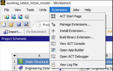
Click on Extensions-> Install Extension. Select the extension from the folder where it is downloaded.
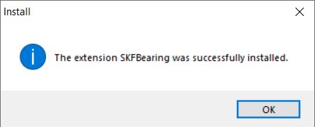
A dialog box will appear showing that the extension is successfully installed.
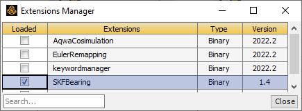
To check if the extension is installed successfully, you can open Extensions-> Manage Extensions. The Extensions Manager dialog box will appear where you can see the extension loaded as a binary along with its version number. You can also uninstall the extension by right-clicking on it and then selecting uninstall.
Open the SKF Bearing app in ANSYS Mechanical
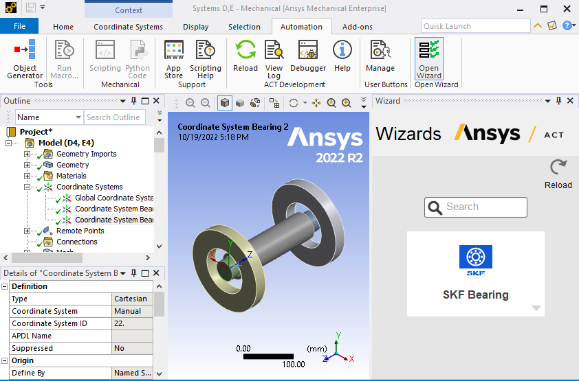
Once the extension is successfully installed, you can open ANSYS Mechanical and navigate to the Automation tab. Then click on the Open Wizard toolbar. The SKF Bearing app will appear on the screen.
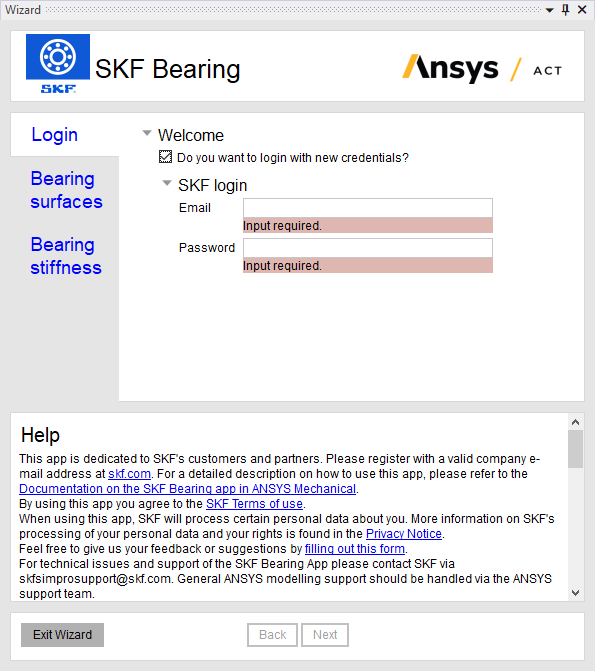
Login
Click on the SKF Bearing app to start using it. Once you click on it, a Login page will be displayed. Please enter your email and password registered with skf.com. Click on Next. A token is now generated and stored so that you do not have to login the next time you use the app. You can directly click on Next. If you want to login with different credentials, you can click on the checkbox as shown in the screenshot below.
Select bearing surfaces, local coordinate system, and analysis block
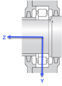
Please note that a pre-requisite to this step is to define the local coordinate system of the bearing in consideration before you enter the wizard. The local coordinate system must, firstly, have its origin aligned with the geometric center of the bearing which generally lies on the centerline of the shaft on which it is mounted. Secondly, the z-axis of the local coordinate system must align with the axis of rotation of the bearing. For a more detailed description, please refer to the section on additional information on bearing local coordinate system.
At the location of the bearing a surface is to be created on the shaft which will be later on connected to the 'SKF Bearing'. Similar for the housing. If the bore of the housing is wider than the width of the bearing then a dedicated section can be created on the bore of the housing. See image below.
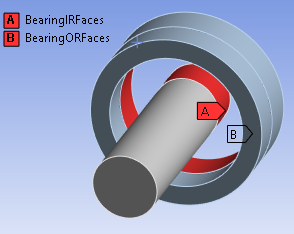
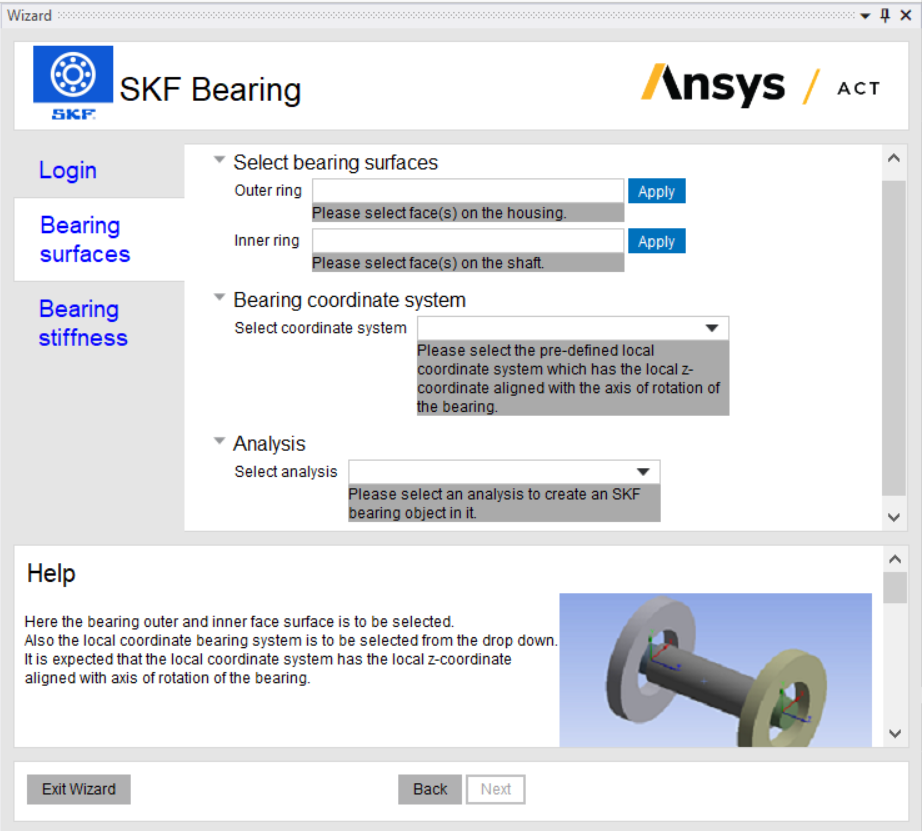
Having the local coordinate system and shaft and housing connection surfaces available, proceed to perform the following steps:
- Select the face(s) that are on the housing and which are connected to the 'Outer ring' of the bearing and click on Apply beside the field titled 'Outer ring'. Repeat the process for the face(s) on the shaft which are to be connected to the 'Inner ring'.
- Select the local coordinate system of the bearing that is dynamically populated in the drop-down menu.
- If there are multiple (static/transient) structural analyses in the model, another drop-down appears where the appropriate analysis block can be selected.
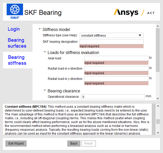
Select a bearing stiffness model
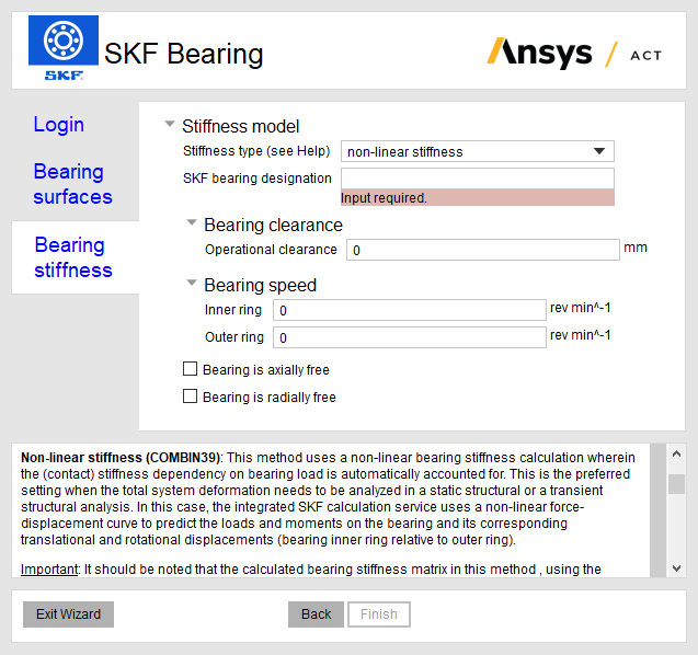
Provide the following inputs related to the mathematical model to complete the creation of a bearing:
- Stiffness type: Choose between a non-linear stiffness or a constant stiffness approach. A detailed analysis on the applicability and limitations of each of these options is described below.
- Bearing designation: Enter a valid designation of any standard SKF bearing. Please note that superprecision bearings are not supported.
- Operational clearance: The input used here is treated as the clearance in operation (after mounting and including possible clearance changes due to thermal expansions). see section on bearing local coordinate system and bearing clearance for more information of the clearance is in radial or axial direction for the specific bearing type. For information: the input given for operating clearance will used and not the specific clearance class like 'C3' which could be part of the designation, e.g. '6005/HC5C3'.
- Bearing speed: Enter rotational speeds to indicate centrifugal forces on either ring of the bearing.
Click on Finish. A message will appear indicating that the bearing is successfully created.
Non-linear stiffness (COMBIN39)
This method uses a non-linear bearing stiffness calculation wherein the (contact) stiffness dependency on bearing load is automatically accounted for. This is the preferred setting when the total system deformation needs to be analyzed in a static structural or a transient structural analysis. In this case, the integrated SKF calculation service uses a non-linear force-displacement curve to predict the loads and moments on the bearing and its corresponding translational and rotational displacements (bearing inner ring relative to outer ring).
Important: It should be noted that the calculated bearing stiffness matrix in this method, using the COMBIN39 element, contains diagonal terms only. This method should thus be applied to those cases alone where the coupling terms, e.g. relating radial and axial loads, do not affect bearing performance. Typically, this applies when there are no induced axial loads when applying a radial load or vice versa, which is the case in the following situations:
- purely radially loaded deep groove ball bearings (DGBB), cylindrical roller bearings (CRB), spherical roller bearings (SRB), CARB toroidal bearings (CARB), needle roller bearings (NRB), or self-aligning ball bearings (SABB).
- purely axially loaded thrust bearings, such as a radially-free spherical roller thrust bearings (SRTB), thrust ball bearings (TBB), cylindrical roller thrust bearings (CRTB), or needle roller thrust bearings (NRTB).
For those bearing types or situations where there is a significant chance of coupling between radial and axial loads, it is highly recommended to carefully check the resulting bearing loads (e.g., the induced axial reaction forces for a given radial displacement will be missing) and consider using the "constant stiffness" approach when in doubt. Typically, this can occur with the following bearing types when being radially loaded: tapered roller bearings (TRB), angular contact ball bearings (ACBB), spherical roller thrust bearings (SRTB).
Constant stiffness (MPC184)
This method uses a constant bearing stiffness matrix which is determined by user-defined bearing loads, i.e., expected bearing loads need to be entered by the user. The main advantage of this method is that it uses an element (MPC184) that describes the full stiffness matrix, i.e., including all off-diagonal (coupling) terms. This makes this method useful when coupling terms could clearly affect bearing performance, such as for the above-mentioned situations. Also, this is the recommended method when performing a linearized analysis such as a modal or harmonic (frequency response) analysis. Typically, the resulting bearing loads coming from the non-linear (static) analysis can be used as input for the constant stiffness approach in the linear (dynamic) analysis.
Important: As this method requires entering the expected bearing loads, it is important to verify those input loads against the resulting bearing loads after having performed the analysis. In case of a large deviation, it is required to check the correctness of the input loads and supply bearing loads which are appropriate for the actual application condition. One way to retrieve relevant bearing load estimates is to use an SKF bearing application simulation tool such as SKF SimPro Quick.
The load values entered are for the estimation of the constant stiffness only, the loads do not end up as (external) loads in the Ansys model.
Finally, it is important to note that - because of the fixed (constant) stiffness matrix - the resulting bearing displacements are approximative, because the non-linear part in the force-displacement curve is missing. Introducing a bearing clearance in this method will affect the load distribution inside the bearing and the resulting stiffness matrix, it will however not lead to additional displacements related to the introduced clearance.
Solving and generating results
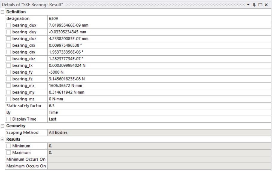
If all the above steps have been completed without any issues, you will find that the bearing object named SKF Bearing and its corresponding result object named SKF Bearing-Result are populated in the model tree.
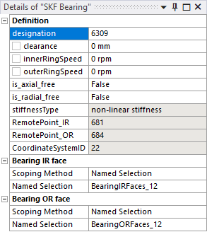
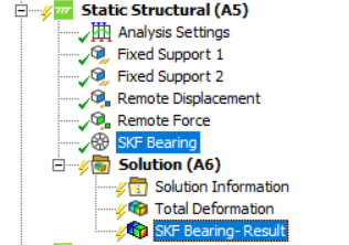 The SKF Bearing object contains the inputs as entered in the wizard and the corresponding
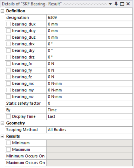
SKF Bearing-Result object contains the bearing stiffness parameters populated as zero by default.
bearing _dux, bearing_duy, bearing_duz are the bearing displacements in local
x, y, and z direction.
bearing_drx, bearing_dry, bearing_drz are the bearing rotations around local
x, y, and z axes.
bearing_fx, bearing_fy, bearing_fz are the forces on the bearing in local
x, y, and z direction.
bearing_fx, bearing_fy, bearing_fz are the moments of the bearing around local
x, y, and z axes. Click here
to read more on the static safety factor.
The SKF Bearing object contains the inputs as entered in the wizard and the corresponding
SKF Bearing-Result object contains the bearing stiffness parameters populated as zero by default.
bearing _dux, bearing_duy, bearing_duz are the bearing displacements in local
x, y, and z direction.
bearing_drx, bearing_dry, bearing_drz are the bearing rotations around local
x, y, and z axes.
bearing_fx, bearing_fy, bearing_fz are the forces on the bearing in local
x, y, and z direction.
bearing_fx, bearing_fy, bearing_fz are the moments of the bearing around local
x, y, and z axes. Click here
to read more on the static safety factor.
 |
 |
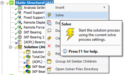
Now, right-click on the appropriate Analysis block and click on Solve to calculate the stiffness of the bearing. Once the solving process is complete the SKF Bearing-Result object is populated with the various bearing stiffness parameters as shown in the screenshot below.
 |
 |
Additional information
Bearing local coordinate system and bearing clearance
This section provides more details on defining the origin of the local coordinate systems and what operational clearance denotes when modeling specific bearing types.
| SKF bearing type | Local coordinate system | Clearance type |
|---|---|---|
| Single row deep groove ball bearings (SrDGBB) | 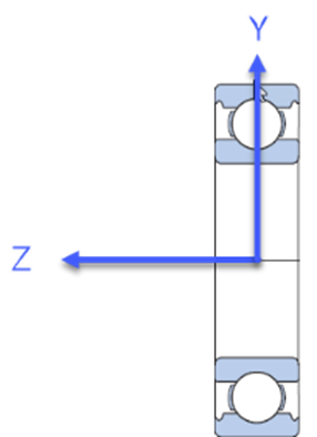 |
Radial clearance |
| Double row deep groove ball bearings (DrDGBB) | 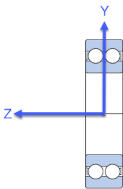 |
Radial clearance |
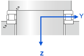
| Single row angular contact ball bearings (SrACBB) | 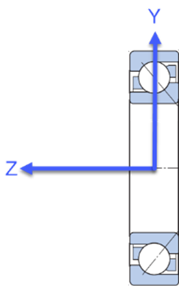 |
Axial clearance Zero denotes nominal conditions Negative axial clearance is currently not supported |
| Double row angular contact ball bearings (DrACBB) | 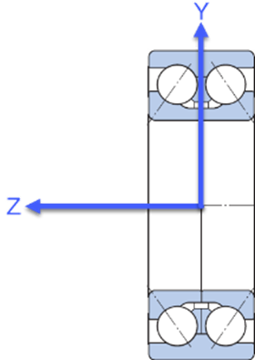 |
Axial clearance |
| Self-aligning ball bearings (SABB) | 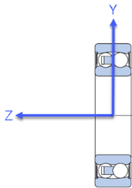 |
Radial clearance |
| CARB toroidal bearings (CARB) | 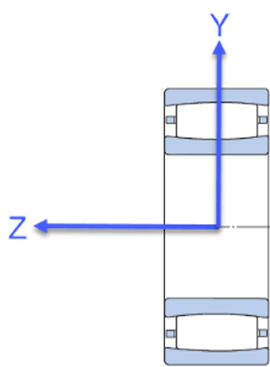 |
Radial clearance |
| Spherical roller bearings (SRB) |  |
Radial clearance |
| Single row tapered roller bearings (SrTRB) | 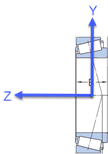 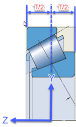 |
Axial clearance Zero denotes nominal conditions Negative axial clearance is currently not supported |
| Double row tapered roller bearings (DrTRB) | 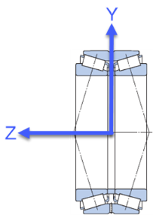 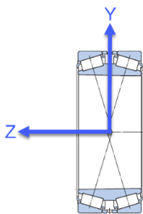 |
Axial clearance |
| Single direction thrust ball bearings (ThBB) | 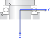 |
Axial clearance Zero denotes nominal conditions Negative axial clearance is currently not supported |
| Double direction thrust ball bearings (DdThBB) | 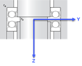 |
Axial clearance |
| Cylindrical roller thrust bearings (CRTB) Needle roller thrust bearings (NRTB) |
 |
Axial clearance Zero denotes nominal conditions Negative axial clearance is currently not supported |
| Single row cylindrical roller bearings (SrCRB) |
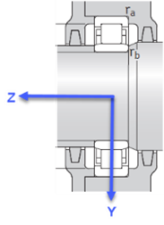    
|
Radial clearance |
| Double row cylindrical roller bearings (DrCRB) | 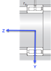 |
Radial clearance |
| Single row needle roller bearings including drawn cup(SrNRB) | 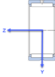 |
Radial clearance |
| Double row needle roller bearings including drawn cup(DrNRB) | 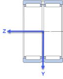 |
Radial clearance |
Known issues
| Issue description | User action |
|---|---|
Decimal point is placed in the wrong position when viewing results of a bearing result object. For example,
the results within the green box are correct while those shown in the red box have the decimal point in
the wrong position. 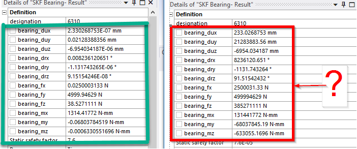
|
The likely cause of this issue is that a regional language is chosen as the default format in Windows. To
rectify this issue, open Control Panel and click on Change date, time, or number formats. It is
recommended to change the format to English (United States). 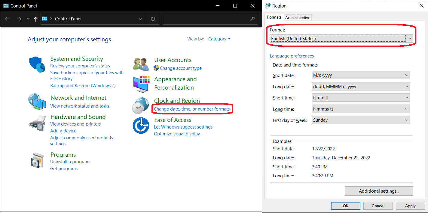
|
| Calculation is not stopped even after encountering an error from the backend. | Results are invalid if such an error message is encountered. Try to resolve the issue by following up with the error message. |
| Hyperlink can not be accessed from the help section by simply left-clicking on them. | Right-click and copy the link to a browser. |
| Logging in using SKF credentials is unsuccessful or error message pops up saying "Failed service call: Unauthorized". | The login token stored locally is likely missing or not valid anymore. Restart the wizard and enter your credentials again to resolve the issue. |
| On solving the model, it can happen that a solution can not be found, especially when introducing clearance inside the bearings. |
Check that the bearing coordinate system is correctly set up (z-axis aligned with axis of rotation of the shaft).
Consider turning on "Quasi-static Solution". Please check the correctness of the results. |
| When adding multiple bearings in Ansys 2022 R1/R2, the 'SKF Bearing' object is not automatically incremented to 'SKF Bearing_2', 'SKF Bearing_3', ... | Manually rename 'SKF Bearing' and 'SKF Bearing - Result' objects to have unique names. |